Vivek Ramanath, Chief Technology Officer, SEDS
The motivation to write an article on mechanics is a short video of a physics experiment by Mr. Rhett Allain. I am making an attempt to explain the concepts of statics and dynamics using this video as a starting point. The article is divided in to four parts, this being the first one.
Part I – Discussion of the experiment in the video. Introduction to Statics and Dynamics
Part II – Engineering theory – Statics versus Dynamics, Linear versus Non-linear
Part III – Fundamentals of Vibrations – measurement and analysis of ship vibration
Part IV – Dynamic simulations – Explicit versus Implicit solver schemes, Frequency-domain versus Time-domain analyses
The link to the video is given below. Please do watch it before reading further.
https://youtube.com/shorts/tcp6JF5vFfg?si=w90TDQh5J6_Tvz_O
Discussion on the video
The experiment set-up is as shown below. Two set of strings with weights in between are suspended from a horizontal bar propped up from a table.
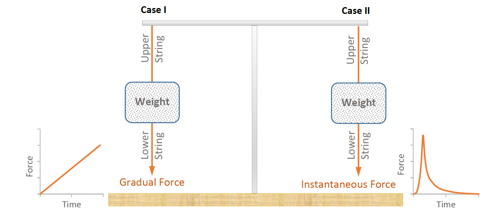
Figure 1: Experiment set-up
In the video, Mr. Allain demonstrates that a mechanical system behaves completely differently under two different load scenarios. In the first case (Case I), the bottom string is gradually pulled down whereas in the second case (Case II), the bottom string is given a sudden downward tug.
The failure happens in the upper string in Case I and the lower string in Case II.
Before going into the details, the following assumptions/simplifications are made:
a. Top and bottom strings have the same cross section and material.
b. The strings have negligible mass. The weight/mass is considered as a rigid body.
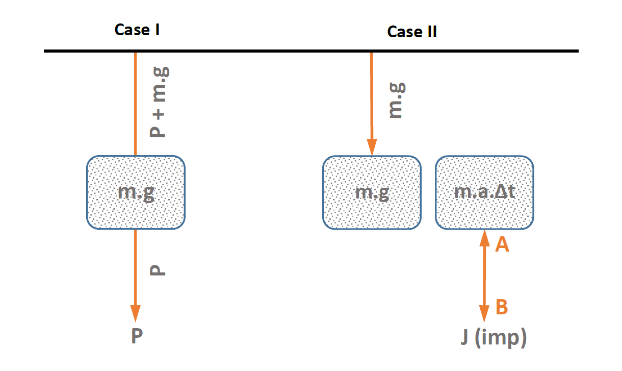
Figure 2: Problem statement – Case I and Case II
The first case (Case I) is a good example of ‘statics’, and the system can be represented by a free-body diagram. As expected, the upper string fails when the combined tension due to the applied force and the weight of the attached mass reaches the ultimate load/capacity of the string. In other words, the string will fail when the true stress reaches the ultimate stress of the material.
Examples of static loads are:
a. A stationary object resting on floor
b. Buoyant force on a floating object in calm water
The second case (Case II) can only be explained with fundamentals of dynamics; more specifically – kinetics. Here the bottom string is acted on by an impulse (J), a large force which acts for a very short duration. Impulse can alternatively be considered as the application of a sudden change in velocity, or acceleration at the point of application – which is Point B. However, the mass connected to Point A cannot instantaneously respond to the sudden change in its state of rest due to inertia. Therefore, Point A will remain mostly stationary. This results in the lower string elongating and straining excessively until it fails in tension. Meanwhile, the upper string hardly experiences the impulse, thanks to the inertia of the mass below – which isolates the impulse from reaching it. Before the impulse travels to the upper string, the lower string breaks, thus removing the load from the system.
The external loads can be solved using conservation of momentum equations. Internal loads and failure can be predicted using strain energy based formulations.
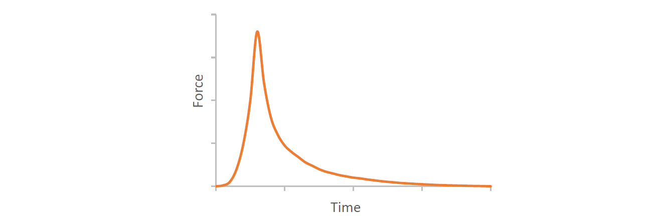
Figure 3: Impulse loading representation
Generic examples for impulse are:
- Shock wave from a blast/explosion
- Slamming of ships in waves
- Impact from dropped objects
- Gun recoil
- Earthquake loads on a building
- Vehicle collision
There are some interesting takeaways for engineers in this video.
- Rate of application of load can make a big difference in the outcome, particularly the location of failure. This can result in major catastrophes. If loading rate was not factored in the design, failure can happen far away from where it was expected to happen. It is a major concern and therefore important for engineers to know when to switch to statics/dynamics, and the pros and cons of each.
- The load at failure and the failure mechanisms can differ between static and dynamic problems. This will be discussed in more detail in subsequent parts of this article.
- The role of the intermediate mass in isolating the upper string gives some clues on the propagation of impulse/shock loads in a spring/mass system.
- During the impulse event, the upper string is mostly statically loaded while the lower string is dynamically loaded.
What other instances do you know where mass is used to isolate/reduce the impulse?
One good example is a dead-blow hammer. A dead blow hammer has an internal cavity with metal pellets or discs (typically coated with polyurethane). The inertia of the pellets creates a phase difference between the hammer body and the pellets, which distributes the peak impact force over a longer duration, thus imparting the same impact energy with a lower peak value. The following force versus time plot shows the reduction and phase difference of the peak force achieved by a dead blow hammer (representative graph).
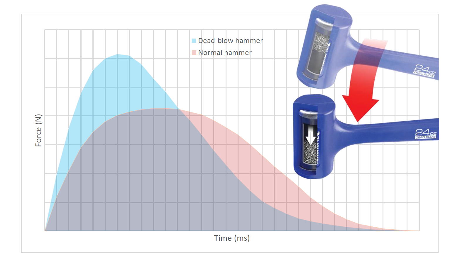
Figure 4: Impulse reduction in a dead-blow hammer
Another important aspect of dead blow hammers is negligible rebound – which is an important feature in applications where precision is paramount – like orthopedic surgeries, manufacture of electronic components, jewelry and so on. The hammer shown is a Kincrome 24 Oz (680g) dead blow hammer. Image courtesy https://www.kincrome.com.au/.
Watch the working of a dead-blow hammer in the following link: https://youtube.com/shorts/E-HOgd8fGpg?si=u1sBYWCNNxF1JJS5.
Statics – Quasi statics – Dynamics
Static Loading
Statics deals with constant and time-independent loads. This means that the net force on an object is zero, and the object remains in a state of rest or in constant velocity motion. The object is not accelerating and is not experiencing any net external or inertial force in this case.
Quasi-static Loading
In the real world, there is hardly any load which is purely static. For example, a cargo container onboard a ship in waves accelerates in six-degrees of freedom (translational and rotational). Loads which vary in time, but at a rate not exciting its transient dynamics may be considered as static at that very moment. However, unlike pure statics, inertial loads are to be taken into account. Such a system is termed as quasi-static.
At what frequency is the quasi-static assumption no longer valid? While there is no defined boundary, it is suggested to study the dynamics of the system when the frequency of loading reaches about 1/3rd the lowest natural frequency or higher (of the system and its major components).
Dynamic Loading
Dynamic loading varies in time at a rate which can evoke transient response in a structure/mechanical system. Dynamic loads can be classified into the following types:
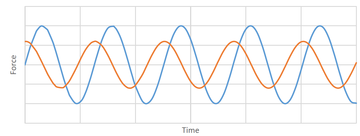
a) Harmonic load – Typically sine or cosine loading where the magnitude, frequency, shape, as well as duration of the cyclic load has a clear pattern. A harmonic load source vibrates in accordance with sin(t+), where is its circular frequency (equal to 2f), t is the elapsed time, is the phase, and f is the frequency. Load from pumps, motors or any out of balance rotating or oscillating mass is generally sinusoidal.
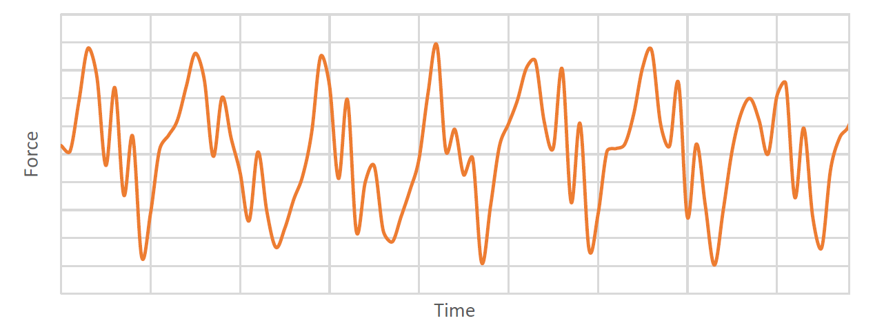
b) Periodic load – These are similar to harmonic loads except that they follow an arbitrary time-dependent repeating pattern rather than being strictly sinusoidal. Examples of periodic loading can be propeller forces on a ship, wave loading on an offshore structure, and wind forces induced by vortex shedding on tall slender structures Below plot shows the periodic nature of gas pressure of a marine engine cylinder in operation.
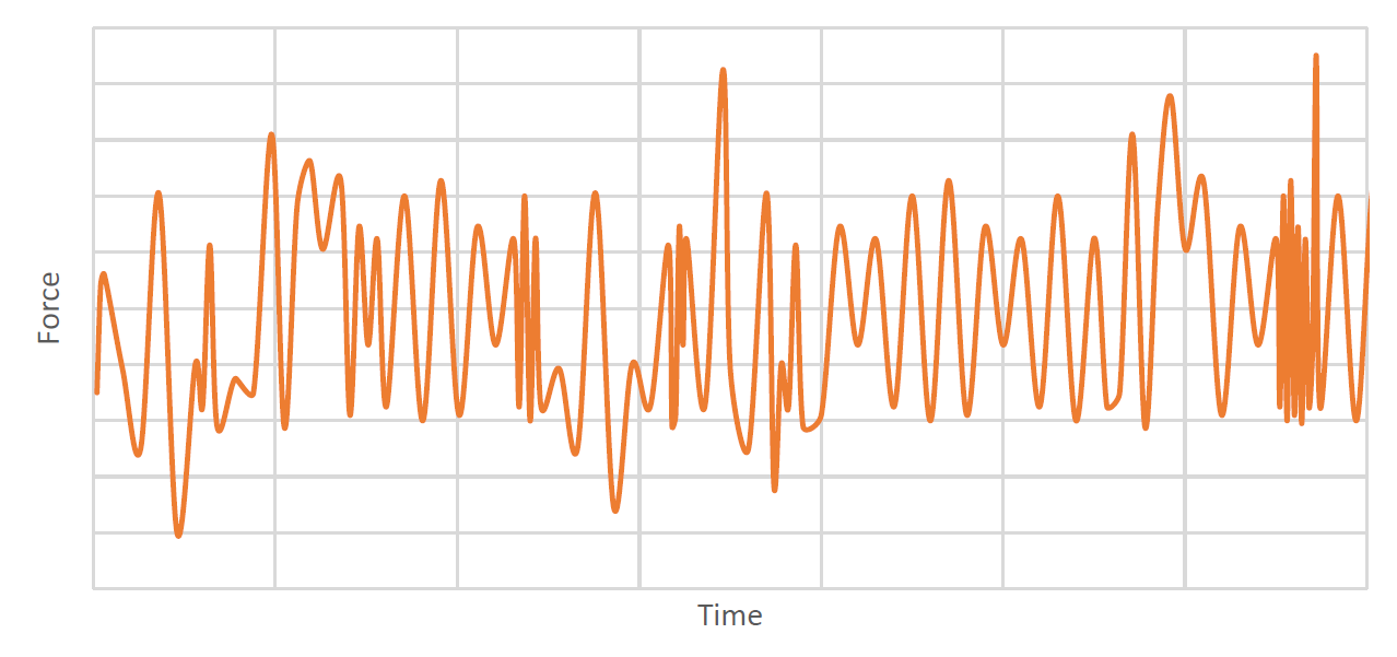
c) Random Load – Random loads do not follow a predictable pattern. They are arbitrary and irregular. The below plot shows the random behavior or seismic load as measured in a Ritcher scale.
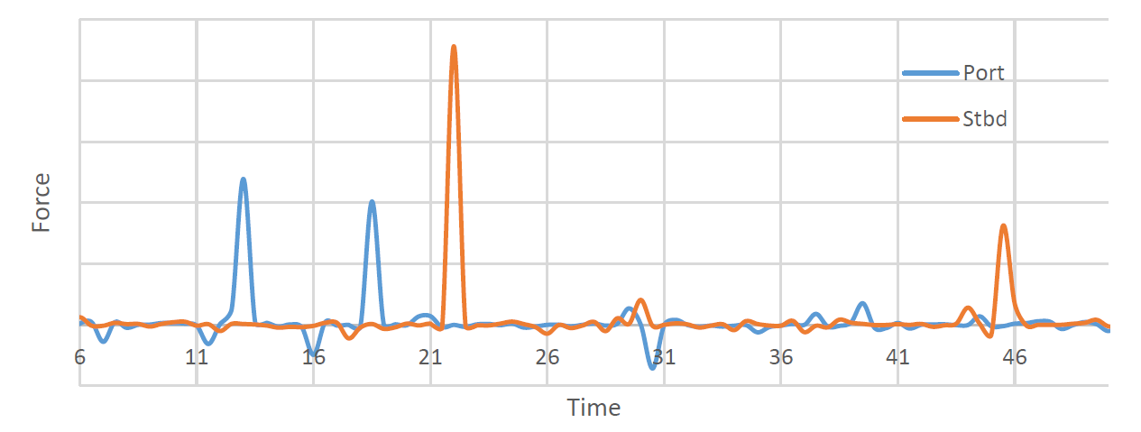
d) Transient load – Transient loads refer to short-lived forces that act on structures for a brief period before dissipating. These loads typically result from sudden changes in velocity or direction. The below plot shows the transient peaks due to bird strikes in the Port and Starboard engines of an aircraft.
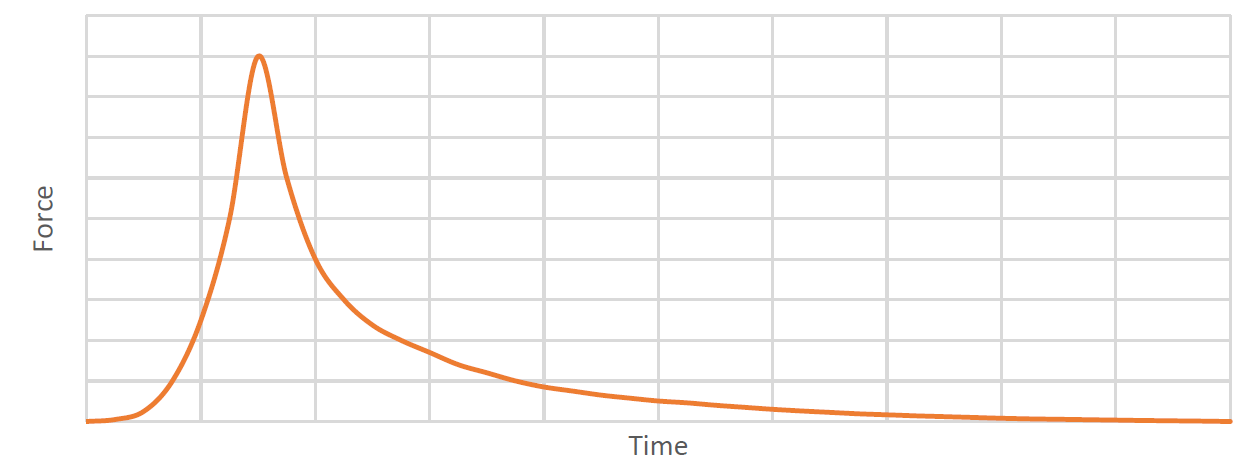
e) Impact/Shock loads – This is a type of transient load of very high amplitude applied dynamically as one-half cycle or a full-cycle. Impact/shock load replicates sudden and abrupt events such as collision, explosion, dropped object and so on. It exerts high-intensity force within an extremely short duration – typically under 1/10th of a second. The plot below shows the blast force from a Naval gun.
Inference:
Rate of loading – in other words, dynamics of loading is an important consideration in structural/mechanical design. Structural response to dynamic loading can be significantly different from static loads (of similar magnitude) in terms of severity and location of failure. The infamous failure of Tacoma bridge, Washington in 1940 due to wind induced vibrations and aero-elastic flutter serves as a stark reminder of ignorance of the dynamics involved. You can see the video here – Tacoma Bridge Collapse: The Wobbliest Bridge in the World? (1940) | British Pathé (youtube.com).
In subsequent parts of this series, I shall try to cover some theory and simulations of dynamic loading in structures. I shall also include some real-world problems from my experience in SEDS, where I lead the ‘Advanced Analysis’ team looking at Mechanics, Fluid Dynamics, Acoustics & Electromagnetics.
References:
- Shock & Vibration Handbook, Cyril M Harris & Allan G Piersol, McGraw-Hill Publications.
- Introduction to Structural Impact, Christopher Wright, 2020, PDH Center.
- Ship Vibration, Global, and Local Modes, Holgar Strumm, Encyclopedia of Maritime and Offshore Engineering, 2017, John Wiley & Sons, Ltd.
- Introduction to Statics & Dynamics, Rudrapratap & Andy Ruina, 2001, Oxford University Press.
- Insights into Ship Vibration Analysis, American Bureau of Shipping, 2023.
- SSC 470, Finite Element Modelling Methods: Vibration Analysis for Ships, Ship Structure Committee, 2015.
[DOWNLOAD PDF]
Disclaimer: The article is for educational purpose only. Images may be subject to copyright.
